Baile Bhúirne to Macroom Active Travel Project Topo Survey
Project overview
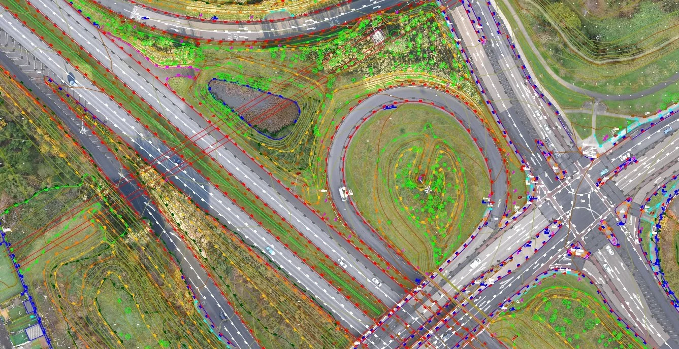
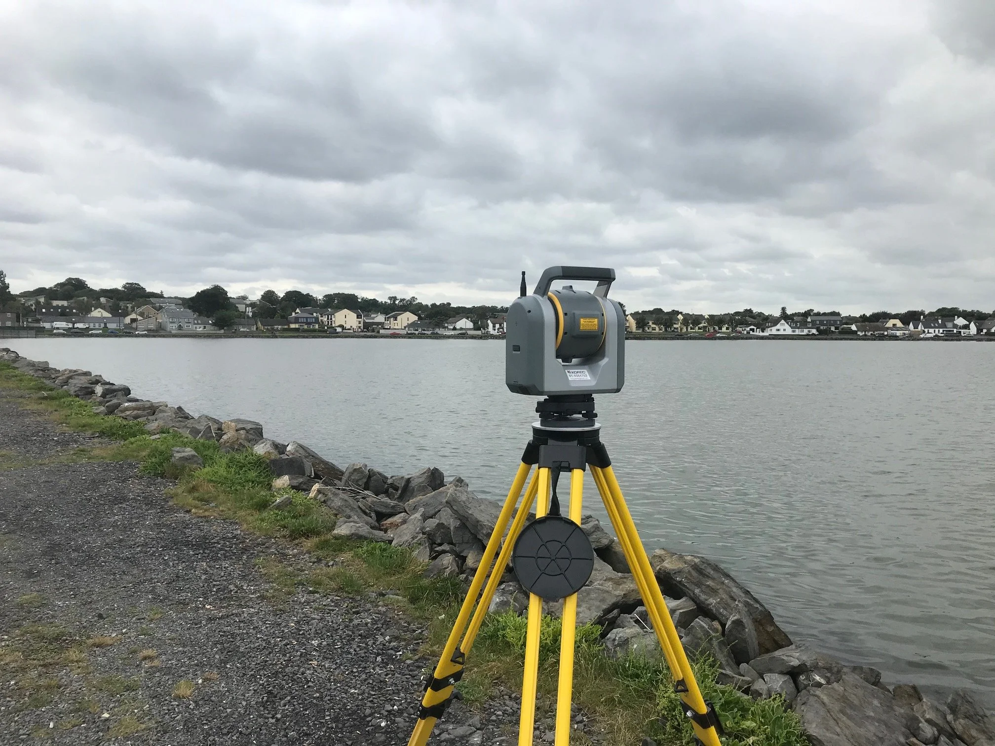
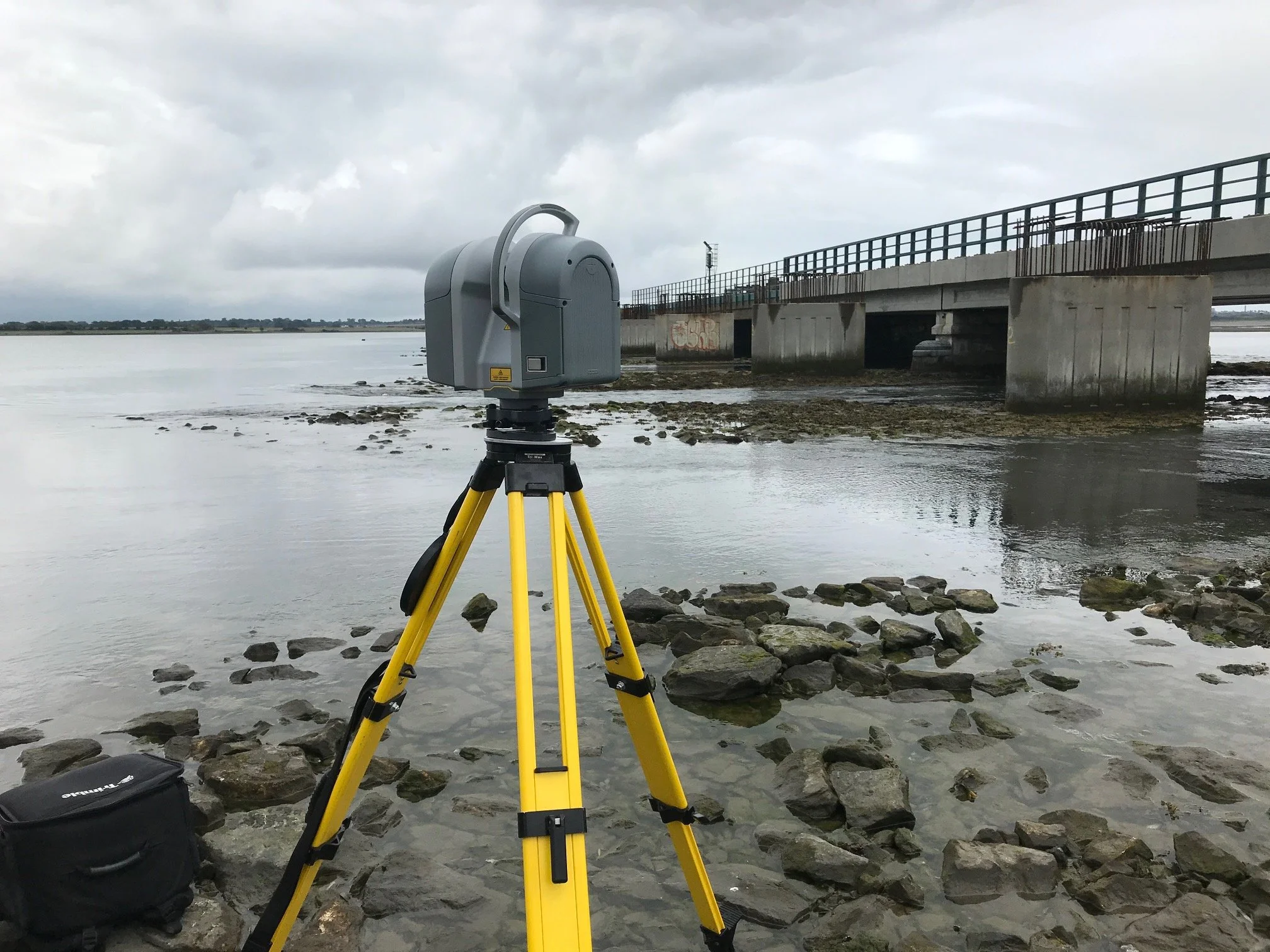
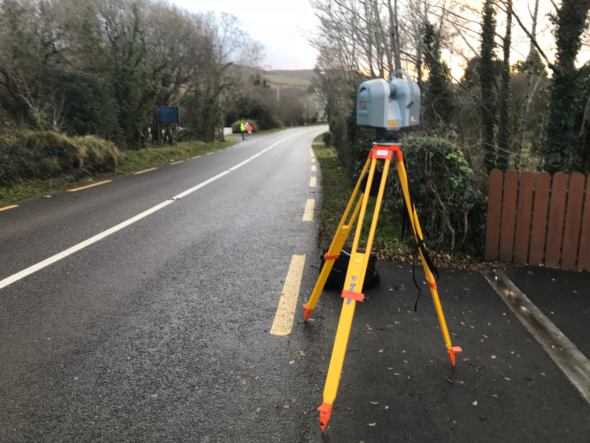
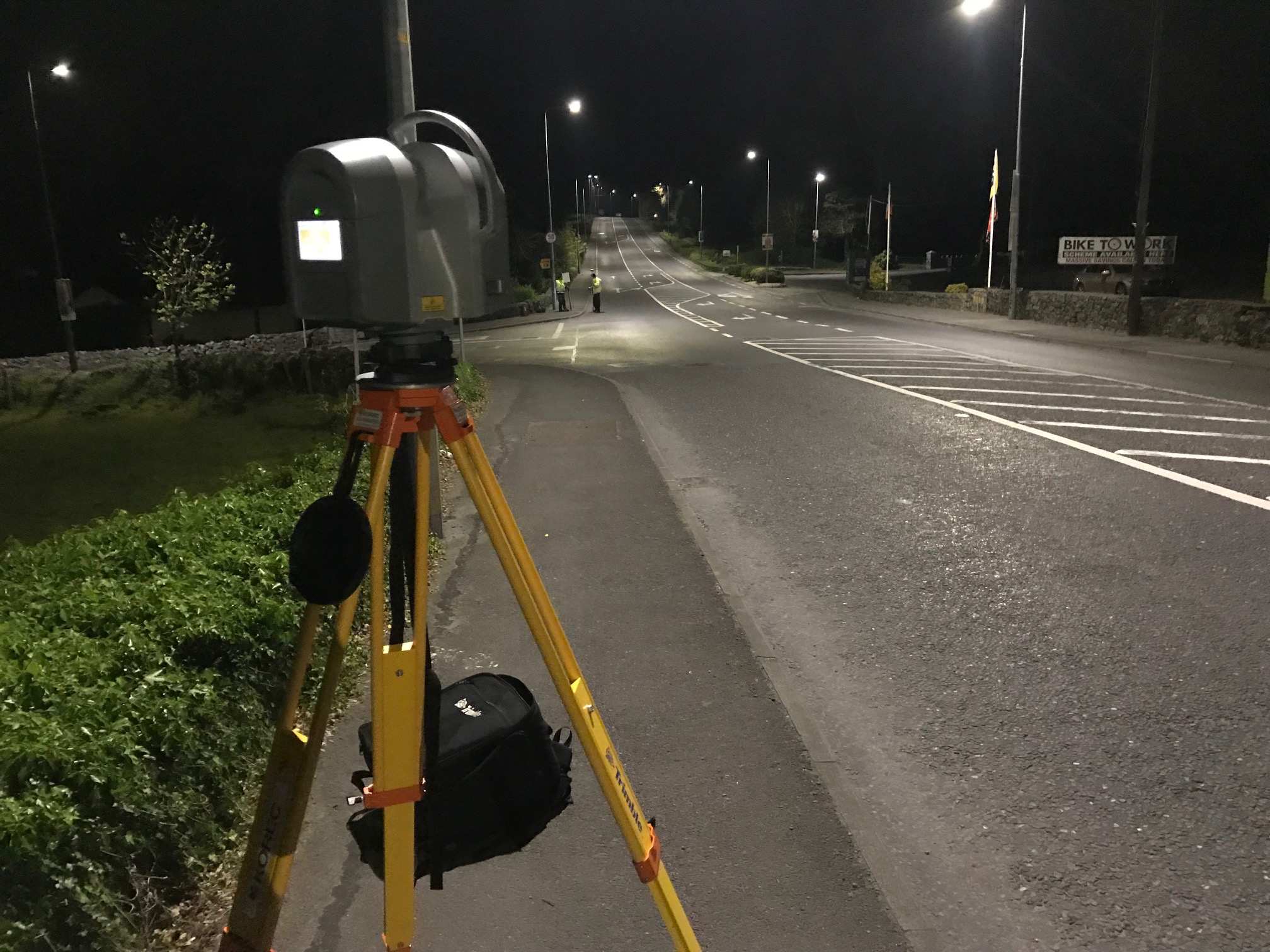
This project consisted of surveying a 22km road corridor between Ballyvourney and Macroom along the old N22 which has now been replaced by the N22 Macroom bypass. The survey was carried out to facilitate the design and build of walking and cycling lanes along the route. As part of the survey we also surveyed the main streets of the busy towns of Macroom and Ballyvourney. The survey was carried out using a combination of mobile mapping and conventional surveying methods such as GPS, Total Station and terrestrial laser scanning.
Project solution
The roads were safely and accurately captured using a combination of Leica Pegasus 2 mobile mapping system combined with terrestrial laser scanning.
Off road areas and services were surveyed using total station and GPS techniques.
Control points were installed every 80m using total station methods and then levelled to ensure the height accuracy met the project specification.
Project accuracies Ground - Horizontal accuracy of +/-10mm for hard detail such as buildings, roads and walls and +/-25 mm for soft detail such as vegetation and surface changes. Vertical accuracy (levels) +/-10 mm for hard detail and +/- 40 mm accuracy for soft -detail.
Project delivery
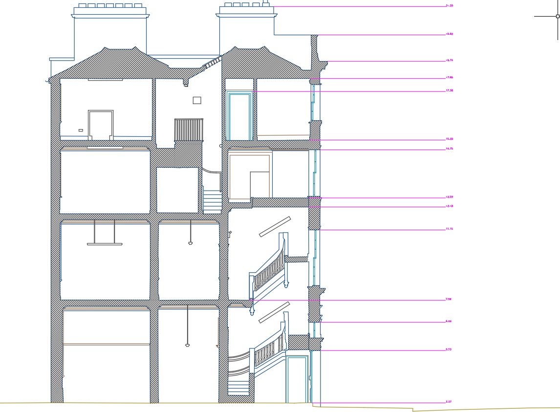
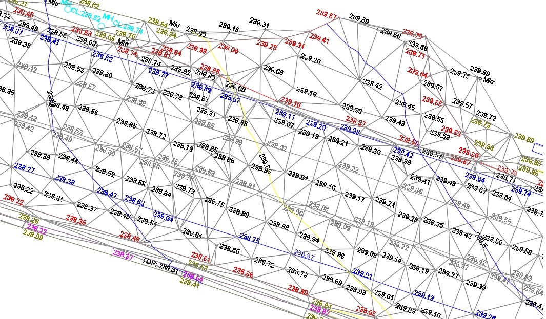
2D/3D Ground Topographical Survey in AutoCAD format.
Point cloud in E57 format.
TIN model in ASCII format.
Provision of survey report..
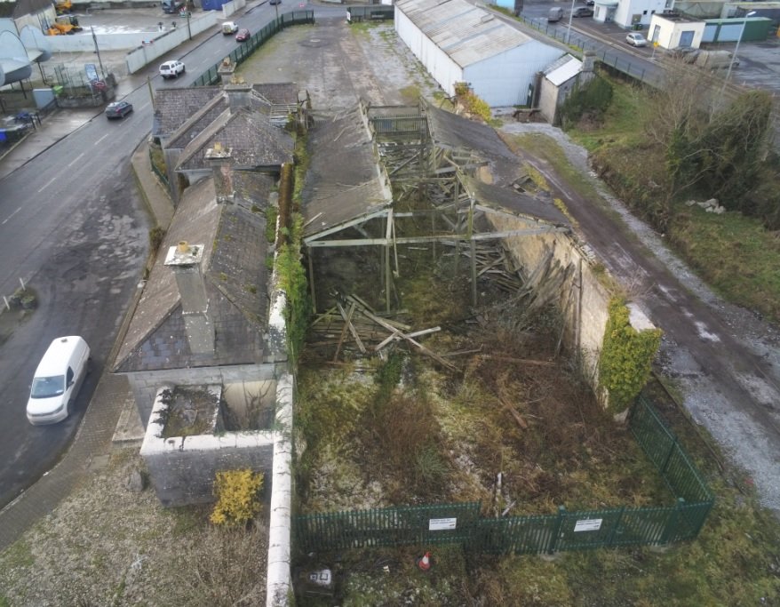
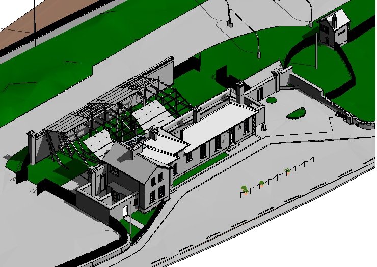
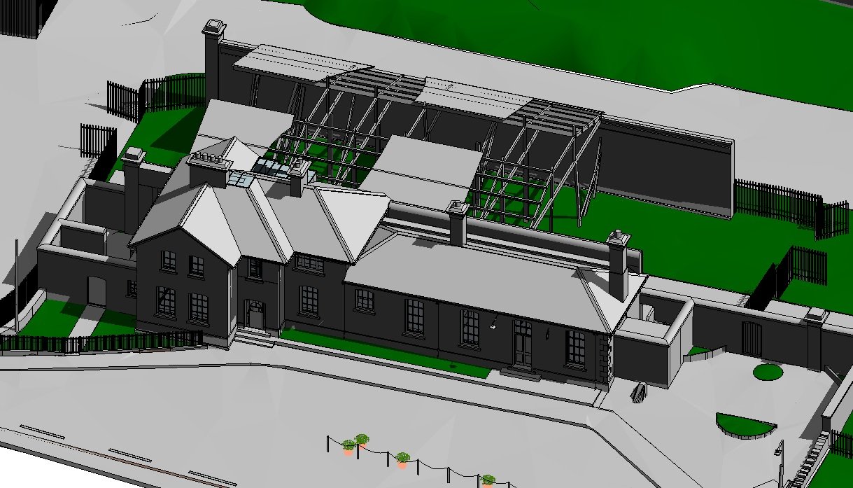
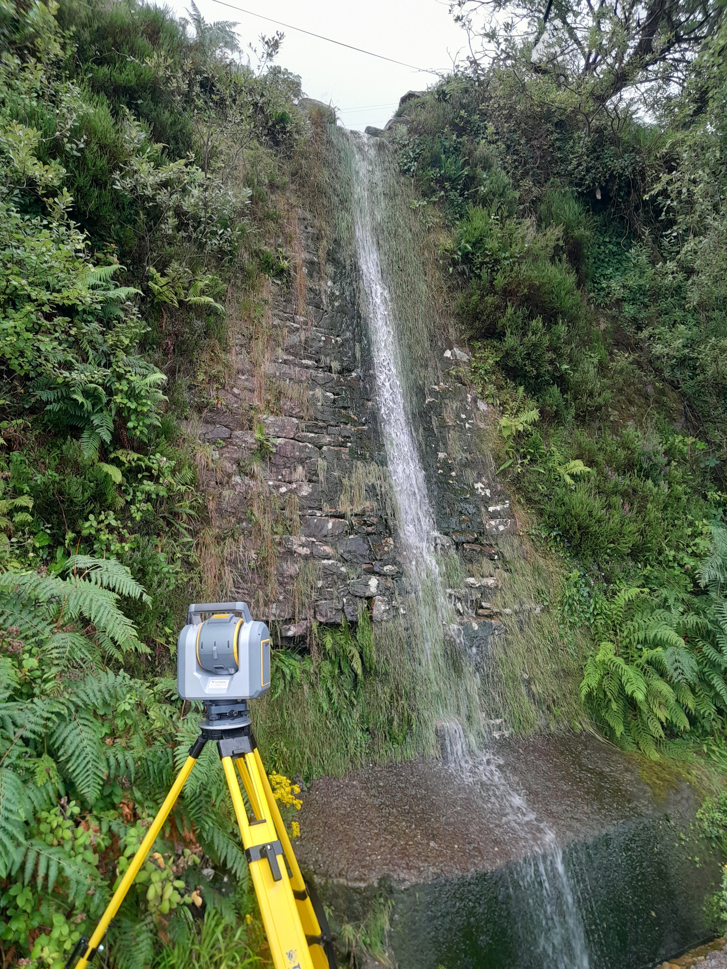
Gallery
Click images to expand.